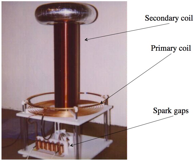
Physicist: Stripped down to it’s most essential parts, a Tesla coil is a wire sticking out of the ground. To get sparks to fly out of the top the rest of the machine “sloshes” electrons up and down the wire.
The picture you should have in your head is a long bathtub, open to the ocean on one end. The machinery of the Tesla coil is like some dude in the bathtub sliding back and forth, splashing water (electrons) out of the closed end, while the tub is refilled from the ocean (ground).
The electricity in the primary coil is what’s doing the pushing, and the electricity in the secondary coil is what’s being pushed. To understand how the driving mechanism works requires a new metaphor and some answer gravy.

Aside from inspiring fear, Tesla coils are useless. Truly, Tesla was a genius. The strange shape is an attempt to avoid arching from the torus to the primary coil, which is bad.
Answer gravy: To get sparks to really fly you need very high voltage (up to several million volts) at a fairly exact frequency. The current that flows up and down the secondary coil, and sloshes out the top, has a high resonant frequency (~MHz, unless the coil is ridiculously huge) that you really can’t do much about. But the current coming out of the wall has a frequency of only 60 Hz (50 Hz for our Old World readers).
So how do you change frequencies? The answer is you “pluck” the primary coil. For example: If you pick a guitar string once a second you have a frequency of 1 Hz, but the string vibrates on its own at whatever frequency it’s made for (~10 kHz).
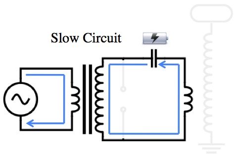
The AC mains have a low frequency (60 Hz) while the secondary coil needs to be driven at a high frequency (~1,000,000 Hz). That means that the secondary will slosh back and forth thousands of times every time the current from the wall turns over just once. Since the fast part of the circuit is so much faster than the slow part, you can just pretend that the current from the transformer is DC (direct current = 0 Hz).
The secret to plucking is to change the circuit’s “shape” using a spark gap. Spark gaps have some pretty slick properties. They have an essentially infinite resistance until a high enough voltage is applied across them, at which point they spark (hence the name). The spark you see is the air being pulled apart and ionized. Now ionized gas is a really good conductor, so a spark is like instantly closing a switch.
Also, spark gaps are the cheapest circuit element evar. Can you cut a wire? Now you got a gap!
Also, adding spark gaps to a device is one of the quickest ways to bridge the divide between regular and mad science.

The transformer on the left forces charge to build up in the capacitor on the top. But the voltage across a capacitor is proportional to the amount of charge it's holding, so eventually the voltage is high enough to trip the spark gap.
The only job that the slow part of the circuit has is to charge the capacitor (pull back the string). When the spark gap sparks (pluck!) the fast part of the circuit takes over, and the slow part is essentially ignored until all the energy is exhausted by exciting the secondary coil (string vibrates and slows).

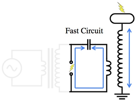
With the spark gap active the charge can flow out of the capacitor and swing back and forth many times, very fast (thousands to millions of times per second). The current through the primary coil then drives current up and down the secondary, causing electrons to "overflow" from the top of the Tesla coil. The "overflow" is a delight to children of all ages.
As current flows through the primary it creates a voltage across the secondary that’s so high that electricity actually flies out of the top of the coil, despite having nowhere in particular to go. It generally takes at least several hundred thousand volts to make that happen.
The loop in the picture above forms an RLC circuit with a high resonant frequency (that matches the frequency dictated by the secondary). As the energy in this system runs out the voltage needed to maintain the spark gap (which is much less than the voltage needed to start it) is lost, and the whole thing returns to the slow, charging phase.
Since the power supply oscillates at 60 Hz, the whole system briefly turns off 120 times every second (the voltage is +, 0, -, 0, +, 0, …). For this reason Tesla coils have a very loud 120 Hz hum that sounds “staticy” and ominous, as opposed to Jacob’s ladders which are continuous, and tend to sound more like “tearing”. Connoisseurs, I’m sure, will agree.


Hello,
I would like to forward this article to a scientist friend who lives abroad,
can I have your permission to do that and the process how to?
Thank you in advance
Afet Jacquemoud
An interested in science reader.
Hi – about the Tesla coil…
This coil seems to be a little toy building on the dynamics of other inventions, perhaps in the experiments that aim att creating wireless electric energy transfers. But I would like to know more, since it is not clear to me how it works… like this:
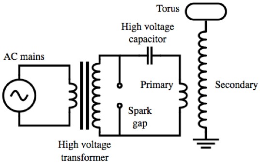
The AC source is clear, it drives a transformer which in order to not be short circuited has a capacitor – and it has a spark gap like a lightning protector. In my world this woud be a circuit that does not do anythinng on its own unless you disturb the balance of it.
This transformer has a secondary big coil but without a ferrum part also and that further transforms the voltage to some higher degree, you don’t mention which kind of coil this is – the induction is not wholly similar to the first coil. The second coil is grounded in one end and has a kind of dissipator in the other. Basically this is it. So the induction in the first coil transforms the voltage up but does not change the frequency. Then it again causes a higher voltage in the secondary coil. The absence of iron in this connection may result in a less defined transformation. In my imagination this would not build more, but maybe through the “elastic” action of the capacitor you would have a buildup in the circuit? So much that the spark gap would activate.
A high frequency applied to a capacitor would start flowing through it, and cause a pretty good connection through the capacitor – like a one to one transformer. Would you say that this is a part of the story? Then the dynamics of the buildup is interesting – plucking is not a word I understand here.
The second coil can access the ground’s high availability of absorption capacity of charge – and that means probably that it could furnish electrons too if your device needs them.
Now the dynamic I don’t understand, what is the type of capacitor needed for this, are there any values that are useful to know, of this and of the coils? The distance between coils to achieve the right induction? Would the energy derived from the earth be of importance?
You speak of current but in my mind you mean voltage, tension, right? In induction experiments one could get sparks to jump but the ampère – current – is very very small. Maybe the transformer itself could be the source of more energy but in that case we would lose a lot of it in the sparking process?
If you could answer this I would be happy – I see that the last comment was 10 years ago, but maybe I’m lucky and you’re still around…
Thinking in terms of energy, the Tesla Coil is a device for moving stored energy from the large primary capacitor to the small capacitance of the output terminal. It does this by associating each capacitor with its own inductor, and providing some magnetic coupling between those inductors. After a few cycles of oscillation in the primary circuit, a perfect design would magnetically transfer all the energy to an oscillation of the secondary inductor with the output terminal. There will be a point within that oscillation where all the energy is stored as voltage on the (small) output capacitor, requiring a very high voltage making a long spark. Tesla Magnifiers can also be analyzed this way, using the standard EE approach of ladder filter networks and coupled resonators. The coupled-resonator approach allows TC and TM designs to be synthesized with good confidence that only small changes from the theoretical design will be required to get good performance in reality.